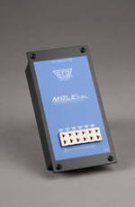
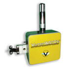
SuperM.O.L.E.® Gold - (다기능 프로세스 컨트롤 제품 및 프로세스 온도 프로파일러
파워 기능)
 SuperM.O.L.E.® Gold는, 최고의 프로 온도프로파일러로, 온 세상의 톱 100의 엘렉트로닉스 제조 회사
거의 모두에 의해서 선택되고 있습니다.
SuperM.O.L.E.® Gold는, 최고의 프로 온도프로파일러로, 온 세상의 톱 100의 엘렉트로닉스 제조 회사
거의 모두에 의해서 선택되고 있습니다.
컴팩트하고 간단하게 사용할 수 있는, SMG®는 6 채널의 계측을
할 수 있어 SPC
(통계적 프로세스 제어-Statistical Process Control)
최강의 소프트웨어의 기능도 제공하고
있습니다.
SuperM.O.L.E.® for Windows®
SuperM.O.L.E.® Gold에 의해서 수집된 정보는
SuperM.O.L.E.® for Windows®소프트웨어로부터
액세스 할 수 있습니다.
온도프로파일 데이터를 해석하는데 필요한 정보 모든 것이, 간단하게 이해할 수 있는 형식에서 표시됩니다.
탭을
클릭하는 것만으로, 최고 온도, 참조치를 넘은 회수, 및 zone(존) 경사가 표시됩니다.
툴바에 의해, 확대, 델타 T계측, 및 허용폭이 사용 가능하게
됩니다.드래그 앤드 드롭을 사용한 동적 예측이 마우스를 클릭하는 것만으로 실행할 수 있어 PCD의 품질을 최적화하기 위해서 인텔리전트인 결단을
내릴 수 있습니다.
SPC 소프트웨어의 기능
- 통계적 법칙을 사용해, X바/R차트를 사용해 PCB 프로세스중의 경향을 식별합니다.
- 차트는, 간단한 드래그 앤드 드롭 조작에 의해 자동적으로 작성됩니다.
원가
절감으로 연결되는
SuperM.O.L.E.®
- 프로세스 파라미터를 최적화해, 재가공이나 스크랩을 삭감합니다.
- 동적인 예측 - 품질을 최적화합니다.
- 준비 시간을 단축합니다.
- 온도 프로파일을 비교하는 오버레이 툴 - 억측을 없애 시간을 절약합니다.
- 내장 SPC 프로세스를 항상 제어된 상태에 유지합니다.
사양
|
온도계측의 범위:
열전 대:
정확성:
해상도:
샘플링 주기:
샘플수:
물리적 치수:
전원:
소프트웨어:
|
-129оC~1300оC (-200оF~2372оF)
6미크로 타입 K (2 세트)
1оC
(1.8оF) 내
0.56оC (1оF)
0.1초~24시간
6채널이 가동 상태로5460
9.41 mm x 89 mm x
152.4 mm (0.37 인치 x 3.5 인치 x 6 인치)
충전식 니켈 수소 파워 팩
Windows®소프트웨어 (내장 SPC 기능부)
|
TEL: 02-868-0661
 AutoM.O.L.E.® Xpert는 진정한 의미의 인텔리전트인 PCB 프로파일 시스템으로 솔더 리플로우를 단순화 해 PCB의 솔더를 개선해 양산라인 전체의 생산성을
증가
시켜드립니다. AutoM.O.L.E.® Xpert
시스템은 하기와 같이 3개가 다른 영역에서 지원합니다.
1. 온도 프로파일러
플래닝
AutoM.O.L.E.® Xpert 시스템에는, 어셈블리 공정으로 사용하고는 솔다 페이스트와 리플로우
오븐의 특정인 조합할 것에, 로바스트인 타겟 프로파일의 설계를 지원하는, 독특한 1조의 소프트웨어 툴이 준비되어 있습니다.이 로바스트인 타겟
프로파일은, 각 설비에의 배포를 위해서, 회사의 네트워크에 공급할 수 있습니다.
이 절차에 의해 회사내에는
물론, 각국의 모든 장소에 있어 프로세스
파라미터 및 PCB의 高 품질을 확실히 복제할 수 있습니다.
2. 리플로우 오븐의 준비
일단 로바스트인 타겟
프로파일이 설계되면, AutoM.O.L.E.® Xpert 시스템이 특정의 PCB로 이 프로파일을 사용하듯이 자동적으로
리플로우를 준비합니다.
리플로우 시스템의 오퍼레이터가 PCB에 관한 간단한 정보를 입력하는 것만으로,
AutoM.O.L.E.® Xpert에 의해 자동적으로 리플로우 오븐의 설정을 타겟 프로파일에 일치시켜, PCB의 품질을
확실히 최적인 것으로 할 수 있습니다.
3. 계속한 프로파일의 확증
일단 리플로우 오븐의 초기설정이 확립하면,
AutoM.O.L.E.® Xpert는 실제의 오븐의 온도 프로파일이 로바스트인 타겟 프로파일과 일치하는 것을 즉석에서 확증
합니다.오퍼레이터는, ECD의 독특한 클립식의 센서 링을 사용해 새로운 SuperM.O.L.E.® Xpert 프로
filer에 PCB를 연결할 뿐입니다.
PCB와 SuperM.O.L.E.® Xpert 프로 filer는 리플로우 오븐내에서
실행됩니다. 실행의 최종 단계에서 오퍼레이터는 단지 SuperM.O.L.E.® Xpert 프로 filer를 오븐에 장착되고
있는 Xpert 도킹 스테이션에 배치할 뿐입니다. 도킹 스테이션에 배치된 프로 filer는 자동적으로 데이터를 오븐의 컴퓨터에
다운로드합니다.
다음에, AutoM.O.L.E.® Xpert 시스템은 실제의 온도 프로파일을 자동적으로 생성해, 자동적으로 이
프로파일을 타겟 프로파일과 비교합니다.그리고 필요가 있으면 자동적으로 오븐을 리셋트 해 항상 타겟 프로파일이 확실히 생성되도록
합니다. 이러한 스텝 모든 것이 오퍼레이터에 의한 조작없이 실행됩니다.
프로파일의 방법
AutoM.O.L.E.® Xpert 시스템을 활용하면, 자동화
납땜조작의 온도 관리가 새로운 단계에
들어가게 됩니다. 지금까지는 수동의 프로파일 장치를 사용해 리플로우 오븐내에서 PCB의 온도 프로파일을 계측해, 최적인 상태가 되도록
오븐을 수동으로 리셋트 해 왔습니다. 새로운 AutoM.O.L.E.® Xpert 시스템은 타겟 프로파일의 플래닝, 리플로우
머신의 파라미터의 준비 및 타겟 프로파일 생산의 자동적인 확인과 프로세스 전체를 통해 사용자가 자동적으로 확인하게
합니다.
사양
시스템 필요 조건
컴퓨터 : AutoM.O.L.E.® Xpert 시스템에는,
리플로우 오븐에 탑재되고 있는 PC가 필요합니다.소프트웨어 옵션안에는, 독립한 데스크탑 PC상에서 사용할 수 있는 것도 있습니다.
특정의 컴퓨터의
필요 조건은 다음과 같습니다.
메모리: 128 MB RAM (최소)
하드 디스크 용량: 50 MB의
빈영역 (최소)
프로세서: 300 MHz Pentium 또는 동등
모니터: 1024 x 768
추천
operating system: Windows® NT4.0, 2000, 95, 98
그
외의 하드웨어: RS232 포토, CD-ROM 드라이브, 마우스
리플로우 시스템:
AutoM.O.L.E.Xpert 대응의 리플로우 머신이 필요
리플로우 머신이 AutoM.O.L.E.Xpert 대응인지
어떤지, 및 소프트웨어의 업그레이드에 관해서는 머신의 제조원에 문의해 주세요.AutoM.O.L.E.Xpert 대응의 리플로우 머신을 현재
제공하고 있는 리플로우 머신 제조 회사의 리스트에 관해서는, 당사의 웹 사이트를 봐 주세요:
AutoM.O.L.E.® Xpert 시스템의
컴퍼넌트
소프트웨어: 프로파일 플래너 모듈, 자동 리플로우 오븐, 세트 포인트 계산기 모듈, 자동
타겟 프로파일, 복제 모듈
하드웨어 : SuperM.O.L.E.® Xpert 프로 filer, Xpert
보호 단일 케이블 TC연결기 첨부의 장벽, 히트 플로우 계측기 부착의 Xpert 센서 링크, Xpert 다운로드/충전 스테이션*, 삼색에 분류
된 열전대세트
*다운로드 스테이션은, 편리한 충전 스테이션이라고 해도 기능합니다.SuperM.O.L.E.®
Xpert 프로 filer가 Xpert 스테이션에 삽입되고 있으면, 프로 filer가 자동적으로 다음 번의 프로파일 실행에 대비해 충전을
개시합니다.
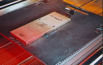
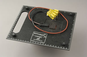
OvenRIDER® : 기능의 최대화, 재가공을 최소화, 미래의
예측
온도와 히트 플로우의 양쪽 모두를 계측하는 독특한 수단
 특허
인정의 OvenRIDER®는 오븐의 성능에 관한 중요한 정보 모든 데이터를 잡을
수 있는 유일한
시스템입니다.
특허
인정의 OvenRIDER®는 오븐의 성능에 관한 중요한 정보 모든 데이터를 잡을
수 있는 유일한
시스템입니다.
SuperM.O.L.E.® Gold를 OvenRIDER®의 메인으로서 사용하는 것으로
오븐을 개입시켜 온도, 히트 플로우, 컨베이어 스피드의 데이터를 수집합니다.
각 시프트의 최초로 OvenRIDER®를 사용하는
것으로써 오븐이 틀림없이 태스크를 실행할 수 있는 일을 확실히 합니다.
즉 제품에 균등하게 열을 전달하는
것을 의미하며 일정한 데이터를 보내는 온도센서와
동작 센서의 편성을 사용하는 것으로써
OvenRIDER® SPC 소프트웨어는 이 데이터를 분석해 해석하기 쉬운 간단한
형식으로 배포하기 위해서 사용합니다.
SPC 소프트웨어
- 간단한 통계적 법칙을 사용해, X바/R차트를 사용해 머신으로 형성되고 있는 경향을 식별합니다.
- 차트는 간단한 드래그 앤드 드롭 조작에 의해 자동적으로 작성됩니다.
- 사용자 정의의 제한에 의해 허용외 상태를 식별합니다.OvenRIDER®는, 리플로우 오븐내에서 온도 및 히트
플로우의 양쪽 모두를 계측 하는 독특한 수단을 제공합니다.
원가 절감으로 연결되는
OvenRIDER®
- 오퍼레이터에게 Go/NO-Go의 데이터를 줍니다.
- 진정한 오븐의 성능을 계측합니다.
- SPC에 의한 퍼포먼스의 예측 - 재가공/스크랩을 삭감합니다.
- 단순하고 객관적인 데이터 - 해석에 의한 작업을 없앱니다.
- 내장되고 있어 간단한 사용법 - 다운 타임을 단축합니다.
- 자동 SPC 리포트 - 엔지니어링에 필요로 하는 시간을 단축합니다.
- CP 및 Cpk 기능 인덱스 - 자동적으로 계산, 제시합니다.
사양
SuperM.O.L.E.® Gold의
호환성
표준폭: 167 mm, 305 mm, 458 mm (6.6 인치, 12 인치, 18
인치)
커스텀폭: 167 mm미만 (18 인치 미만)
높이: 25 mm (1 인치)
길이:
452 mm (17.8 인치)
전원: 충전식 배터리 |
|
시스템 필요 조건
컴퓨터:
Pentium®프로세서 추천, 16 MB RAM (최저한), 24 MB의 하드 디스크 공간 영역, 3.5 인치 HDD
floppy-disk drive, 마우스, 시리얼 포트 칼라 VGA 그래픽 및 모니터 (800 x 600 추천)
프린터: 칼라
프린터 추천
operating system: Windows® 3.1으로부터
Windows® NT (16 & 32비트)
|
WaveRIDER® : 작업한 데이터를 기억하여 미래를 예측할 수 있습니다.
웨이브는 솔더 프로세스는 준비 절차가 가장 까다로운 절차중에
하나 입니다. WaveRIDER®에 의해 웨이브 솔더의 준비가
대폭 간소화되어 완전한 재현성이 반복해 실현됩니다.
PCB의 레시피의 예열 온도, 컨베이어의 속도, 웨이브의 높이, 접촉 시간
및 평행도, 이런 모든 것이 WaveRIDER®시스템의 개념을 사용하며 계측, 감시합니다.
SuperM.O.L.E.® Gold는 프로세스 파워를 제공합니다.
통계적 프로세스
제어
WaveRIDER® SPC 시스템은 데이터 수치를 수집 비교해 데이터를 완전하게 객관적인 방법으로
제시하고 시스템으로 형성될 가능성이 있는 경향을 식별합니다.
이 파워풀한 툴에 의해 제어할 수 없는 상태가 발생하기 전에 사용자가 개입할 수
있어 시간 및 경비에 드는 재가공의 원가를 삭감합니다.
SPC 소프트웨어
- 간단한 통계적 법칙을 사용해 X바/R차트를 사용해 머신으로 형성되고 있는 경향을 식별합니다.
- 사용자 정의의 제한에 의해 허용외 상태를 식별합니다.
WaveRIDER®는 웨이브 솔더링을 하는데
있어 불필요한 절차를 줄여 원가 비용을 절약합니다. 
- 머신 재현성의 보증 - 재가공을 삭감합니다.
- 보수 시간의 삭감 - 시간을 절약합니다.
- SPC에 의한 퍼포먼스의 예측 - 재가공/스크랩을 삭감합니다.
- 단순하고 객관적인 데이터 - 데이터 해석에 의한 작업을 없앱니다.
- 내장되고 있어 간단한 사용법 - 다운 타임을 단축해, 노력을 절약합니다.
- CP 및 Cpk 기능 인덱스 - 자동적으로 계산, 제시됩니다.
사양
SuperM.O.L.E.® Gold의
호환성
표준폭: 229 mm, 305 mm, 381 mm, 458 mm (9 인치, 12 인치, 15 인치, 18
인치)
커스텀폭: 145 mm미만 (5.7 인치 미만)
높이: 33 mm (1.3
인치)
길이: 305 mm (12 인치)
전원: 충전식 배터리 |
|
시스템 필요 조건
컴퓨터:
Pentium®프로세서 추천, 16 MB RAM (최저한), 24 MB의 하드 디스크 공간 영역, 3.5 인치 HDD
floppy-disk drive, 마우스, 시리얼 포트 칼라 VGA 그래픽 및 모니터 (800 x 600 추천)
프린터: 칼라
프린터 추천
operating system: Windows® 3.1으로부터
Windows® NT (16 & 32비트)
|
TEL: 02-868-0661
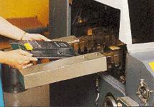
FluxometerTM는 스프레이 플럭스 패턴의 균일성 및 솔더를 최대화해 재가공을
줄입니다.
프로세스의 품질을 개선
세꼐 최초로 간단하게 사용할 수 있는 프로세스 모니터인
FluxometerTM로 스프레이후락스의 프로세스를 제어.
FluxometerTM는 편리하고 정확하게 수집하여 두어서
오퍼레이터는 진단 체크를 몇분에
실행할 수 있습니다. 
- pcb기판과 같이 스프레이 플럭스의 경유로 FluxometerTM를 실행합니다.
- 특별한 테스트 용지를 없애 톱 사이드 기판의 침투와 플럭스 도포의 균일성을 관찰합니다.
스프레이 플럭스의 성능은 로바스트인 웨이브는 솔더 프로세스에 중요한 것입니다. 이것으로 머신의 정확한 조정을 실시해 프로세스를 최적화합니다. 웨이브는 핸더 프로세스에 중요한
스프레이 플럭스의 성능에 의해
프로세스를 개선하는 정확한 머신 조정을 실시할 수 있습니다.
프로세스
제어의 최대화
FluxometerTM는 스프레이 플럭스의 톱
사이드 기판 침투와 균일성에 의해 간단하고 실시간으로 제공합니다.
- 플럭스 조정으로부터 장애를 없앱니다.
- 재가공과 스크랩을 줄입니다.
- 제조 코스트를 절감 합니다.
- 스프레이 플럭스의 프로세스를 개선합니다.
- 웨이브는 솔더의 프로세스를 개선합니다. 정확하고 간단하게 사용할 수 있도록 설계되고 있습니다.
사양
|
팔레트
|
|
표준폭:
229 mm (9 인치)
305 mm (12 인치)
381 mm
(15 인치)
458 mm (18 인치)
길이:
313 mm (12.32 인치)
|
|
커스텀폭: 당사로 문의해 주세요
전체의 높이: 28 mm (1.08
인치)
두께, 팔레트: 8 mm (0.315 인치)
팔레트의 재질: 정전 방지의
합성
|
Mesh
|
|
재질: G10 유리 에폭시 수지
폭: 가변 (팔레트의 폭에
의한다)
(51 mm ( 약 2 인치)만 팔레트폭보다 좁다)
패턴: 2.54 mm (0.1 인치)
|
|
길이: 216 mm (8.5 인치)
두께: 1.58 mm (0.062
인치)
구멍의 직경: 0.889 mm (0.035 인치), 완전한 메끼
|
테스트 용지
|
|
종류: nIPA, 혹은 중성 또는 저pH감도
폭: 가변 (팔레트의 폭에
의한다)
(51 mm ( 약 2 인치)만 팔레트폭보다 좁다) |
|
길이: 216 mm (8.5
인치)
|
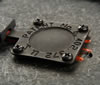
슈퍼
몰(SuperM.O.L.E.®
)
온도 프로 filer-
- 슈퍼 몰 골드(SuperM.O.L.E.® Gold)
- 슈퍼
몰신라인(SuperM.O.L.E.® Thinline)
온도
프로파일의 표준화를 하기 위한 최초의 몰(MOLE)을 소개했습니다. 현재는 프로파일 기기의 최대 시장인 엘렉트로닉스 업계에서 몰(MOLE)은
온도 프로 filer-의 일반 명칭으로서 다른 기기를 평가할 때의 기준이 되어 있습니다.
몰(M.O.L.E.®
: 온도측정프로파일)
몰(MOLE)은
소형 배터리를 전원으로 한 온도 기록 기기로 시간과 온도에 관한 대량의 다양하고
복잡한 정보를 제공합니다.
M.O.L.E.® (은)는
Multichannel Occurrent Logger Evaluator의
약어입니다.
기능:
몰(MOLE)은
K-타입의 열전대를 사용해 온도 정보를 감지합니다. 열전대를 측정하는 프로파일 개소에 접속해 몰(MOLE)을 시동할 만한 단순한
작업입니다.
몰(MOLE)은
설정한 시간이 경과하면 자동적으로 정지합니다. 몰(MOLE)을 PC에 접속해 정보를 다운로드합니다.
몰(MOLE) 용의 소프트웨어는 시간과 온도의
정보를 컴퓨터 스크린에 표시합니다.
동시에 모든 열전대, 또는 선택하는 개개의 열전대의 정보를 표시할 수 있습니다.
소프트웨어는
임의의 측정점의 온도, 1초간의 온도 슬로프의 변화, 규정 온도 이상의 시간, 평균 온도, 표준 편차치등을 간단하게 확인할 수 있도록 설계되고
있습니다.
DOS 또는 윈도우즈 베이스의 소프트웨어를 제공하고 있습니다.
몰(MOLE)의
종류:
슈퍼 몰 골드(SuperM.O.L.E.®
Gold) 온도 프로파일러 (THERMAL PROFILER) |
|
채널수 |
6 채널
|
|
측정
온도 범위 |
-129~1300оC |
|
정도 |
1оC이내 |
|
최소
온도 단위 |
0.56оC |
|
샘플링
간격 |
0.1초~24시간 |
|
샘플수 |
5460(6
채널 사용의 경우)
>32,
000(1 채널 사용의 경우) |
|
치수 |
89x152.4x9.41
mm |
TEL: 02-868-0661
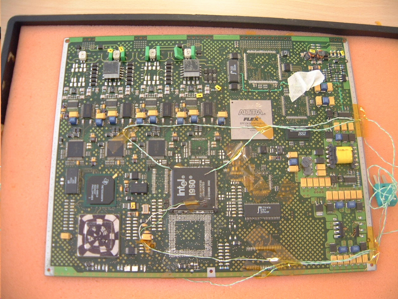
사용 설정 및 온도측정
과정 및 결과 SMT
REWORK SYSTEM 적용예 (여기를
클릭해 보십시오)
Spreadsheet database format with powerful filters to select the
data set desired for SPC analysis:
Added: File names include user
initials, symbol to show that data is unavailable, and an indicator of which
columns are filtered
Easily define the spreadsheet data you wish to view and the SPC
charts created:
Added: You can freeze or fix the LCL/UCL values
X-double bar and R charts are automatically created for the user
selected parameters:
Added: X mR chart added for a subgroup of one

ReworkRIDER™ for Rework Station Profiling
 ReworkRIDER™ Upgrade System ReworkRIDER™ Upgrade System
Elevate your Rework Station quality control to the same level as your wave
soldering and reflow oven processes with the ReworkRIDER.
For current SuperM.O.L.E.® and other profiler users, ReworkRIDER features the
Wiz™ patent-pending dual sided nozzle probe that profiles the directly applied
heat from the rework station. Adjacent to the Wiz top and bottom are air
temperature sensors. During component removal and replacement two additional
thermocouples may be attached in the vicinity for monitoring sensitive
components and laminate.
|
|
The ReworkRIDER:
- Measures top and bottom side surface and air temperatures
- Integrates with SuperM.O.L.E.®Gold and other profilers
- Profiles convection and IR. rework stations
- Documents consistent performance station-to-station, day-to-day
|
 Wiz Sensor |
The kit includes the ReworkRIDER pallet, Wiz and air sensors and
thermocouples connection block. Dedicated SPC software in development will be
released in Q3 2003. Until then we encourage early adopters to download
OvenRIDER® SPC from our pcb21@korea.com.
Standoff pillars protect the sensor area and the product adapts to utilize
either micro or miniature thermocouple connector types.
|
 The ReworkRIDER, when purchased with a MoleSCAN Profilier, is an economical
package that can be used to monitor your rework process The ReworkRIDER, when purchased with a MoleSCAN Profilier, is an economical
package that can be used to monitor your rework process
Items included in the ReworkRIDER kit:
- ReworkRIDER™ Pallet
- SPC Software
- Thermocouple Adapter Set
- ReworkRIDER Hardware/Software Manual
- ReworkRIDER Quick Reference Guide
|
Baker's SuperM.O.L.E.®
GOLD
- The Standard Profiler
of the Baking and Food Processing Industry
- Proven results in
improving both QUALITY and THROUGHPUT
- Increase shelf
Life
- Improve
yield
- Improve visual
quality
- Improve
consistency
- Reduce
costs
- Reduce ingredient
usage
- Reduce
waste
- Ensure Process
Repeatability
- Balance Ovens Easily
and Efficiently
- Complete and Ready to
Run, Including Easy to Use Windows Software
|

|
|

|
The portable,
programmable Baker's SuperM.O.L.E. Gold offers a
unique "wireless" way to measure, record, and document temperature variations in
your baking processes without trailing cables or wires. With Temperature sensors
attached directly to your baking product, SuperM.O.L.E. Gold accurately captures essential temperature
data for any preset time at a sample interval programmed on your PC. Custom
designed for the baking industry, the Baker's SuperM.O.L.E. Gold provides the oven temperature data and
analysis required to ensure consistently high quality
product.
The SuperM.O.L.E.® Gold has plenty of
memory and a rechargeable powerpack. Golds are available with the RF option for real-time oven
analysis. The Gold system may utilize the optional AeroM.O.L.E.® that is extremely
useful for balancing air returns and correctly adjusting interior baffles.
Contact ECD today for more information about the complete solution to your
baking oven quality control needs - the ECD SuperM.O.L.E! |
 The M.O.L.E.’s® Role In Baking
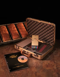
- Records oven temperatures under specific settings
- Records product, dough or mix temperatures
- Measures actual product and ambient temperatures
- Provides valuable insights into oven performance
- Offers tuning / balancing options
- Enables process viability testing in a production setting
- Facilitates baking process sensitivity analyses
Click here to go to our Download page to learn more about our
Baking Kits and Barriers
What is a M.O.L.E.® Profiler?
With the ECD M.O.L.E.® Temperature Profiler - a small, battery powered
temperature recording device that is designed to measure and collect detailed
time and temperature information
How does it work?
The M.O.L.E.® profiler uses Type K thermocouples to sense temperature
information. Simply connect the thermocouples to the product to be profiled and
turn it on.
After a preset time the M.O.L.E.® will turn itself off. You then connect the
M.O.L.E.® to a PC and download the information. Special software takes the time
and temperature information from the M.O.L.E.® and displays it on your computer
screen. You can view all the thermocouples simultaneously or select the ones you
wish to display.
The software is designed to allow you to easily ascertain temperatures at any
point in your process, the slopes amount of change in degrees per second at any
points in your process, how long the object has spent above specific
temperatures, average temperatures, standard deviation and much more!
Read more about our new profiling kit on Bakery Online. Please
click here
Baking Kit, E44-2253-00, Includes:
- SuperM.O.L.E.® Gold
- 2 Battery Packs
- Hardware and Software Manuals
- Quick Reference Guide
- Calibration Certificate
- Charger
- 1" and 1.6" Survivor Barriers (Nested Pair)
- SMG to PC Interface Cable
- USB to RS232 Cable
- M.O.L.E.® Baking Software Suite on CD
- 6 - Color Coded 0.010" Type K Thermocouples - 3 Ft
- 6 - Color Coded 0.010" Type K Thermocouples - 12 Ft
- All Packaged in an Attractive Gold Carrying Case
|
|
SuperM.O.L.E.® Gold
Specifications |
| Channels: |
6 channels |
| Temperature measurement range: |
-200 to 2372°F (-129 to 1300°C) |
| Accuracy: |
+/- 0.1% + 1°C |
| Resolution: |
1°F (0.56°C) |
| Sampling Interval: |
.2 seconds to 24 hours |
| Number of samples: |
5460, with six channels active |
| Dimensions: |
3.5 x 6 x 0.38 inches 89 x 152.4 x 9.41 mm |
NEW  VaporWATCH™ Relative Humidity Sensor:
 |
You can now perfect your proofing process and improve your production yields
with our new humidity sensor along with your Gold M.O.L.E.® Temperature Profiler
(sold separately).
- Reliable, Accurate, and Easy to Use
- Convenient - Quick Download
- Powerful Software Included
This handy sensor comes in an attractive carrying case with out new baking
software, cable and charging power supply.
Click HERE to go to our download
page to get a datasheet on the VaporWATCH sensor
|
| Accuracy: |
3% |
| Resolution: |
0.1 RH |
| Battery Life: |
4 Hours continuous |
| Battery type: |
Rechargable NiMH |
| RH range: |
0 to 100% Non condensing |
| Operating range: |
32° to 122° F, 0-50° C |
Temprobe™
 |
|
 Temprobe™ Temprobe™
Reflow Rider™
E-Z Rider™
Side Rider
Board Carriers
FlexiProbe™
ECD's
SuperM.O.L.E.™
Technical Information
Industry Links
|
|
 New Concept in Thermal Profiling New Concept in Thermal Profiling
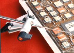
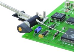
TEMPROBE™ is a patented, precision temperature sensing instrument.
The subminiature thermocouple tip can be placed anywhere on a board, including
profiling in wet solder paste or on fine pitch component legs. TEMPROBE is used
in place of a conventional thermocouple to monitor the temperature of critical
solder joints or components in reflow, wave solder and rework processes.
TEMPROBE is compatible with all thermal profilers.
Quality, Precision, Function
- Prevent PCB Damage - Eliminate
soldering or bonding of thermocouples to PCBs.
- Cut Labor
Cost - Installation and removal take just seconds.
- Produce
Reliable Profiles - High contact pressure and low thermal mass give fast,
reliable response.
- Profile in
Wet Solder Paste - Profile the first pass of a PCB through the oven.
- Monitor
Temperature Anywhere - Small, durable thermocouple tip fits in tight
places.
Clip, Position, Profile and Save!
One of our customers,
who used to tape or solder two thermocouples to each board for profiling, is now
using two TEMPROBEs. He calculated savings of over $6000 per year by switching
from traditional thermocouple attachment to TEMPROBEs. Take a look at his
calculations, then fill in your own worksheet to see what TEMPROBE can do for
you (hit the TAB key after each entry for automatic
calculation).
 |
|
Temprobe™
Getting Started
 Your new TEMPROBE will become
very quick and easy to use, once you understand how to create a solid thermal
contact between the TEMPROBE thermocouple and your test point. This page
includes basic instructions, as well as a number of ways to customize
TEMPROBE.
Your new TEMPROBE will become
very quick and easy to use, once you understand how to create a solid thermal
contact between the TEMPROBE thermocouple and your test point. This page
includes basic instructions, as well as a number of ways to customize
TEMPROBE.
Positioning the TEMPROBE sensor tip
- The
thermocouple sensor tip projects slightly out of the end of the small tube. This
tip must be in contact with the test point in order to provide an accurate
reading.
- First,
center the pivoting range of the ball joint around the test point.
Release the locking lever on the ball joint by holding the large diameter tube,
lifting the sensor tip clear of the PCB and pivoting it about one inch past the
test point.
- Next,
create the correct spring force. Slide the thermocouple tube through the
ball joint and position the sensor tip beside the test point. Press down
gently on the tapered end of the large tube to bend the small tube until it is
parallel to the larger tube. Tighten the locking lever on the ball joint to lock
the sensor tip in place. This produces a pre-load force, ensuring good thermal
contact with the test area.
- Finally,
lift the sensor tip and set it down on the test point. If
necessary, the ball joint can be pivoted slightly. The sensor tip can be placed
directly in solder paste.
Adjusting the mounting clamp
- The flat
Phillips head screw in the bottom plate of the clamp adjusts the clamp jaws to
grip the PCB. The screw can be loosened to accommodate boards up to 1/4 inch
thick.
- Adjust the
screw so the clamp jaws start to grip the PCB when the cam lever is vertical.
Rotate the cam lever down to its horizontal stop for a secure grip on the PCB.
Adjusting the ball joint
- The locking
lever on the ball joint can be set to lock when it is horizontal, to give the
lowest profile to the TEMPROBE.
- To adjust the
locked angle of the locking lever, turn the knurled nut in or out slightly, as
required. The nut has a left handed thread.
- To reduce the
drag of the thermocouple tube through the ball joint, turn the knurled nut about
half a turn, and reset the locking lever angle.
- The
self-locking nut that holds the ball joint to the clamp should be snug enough to
prevent the ball joint from being accidentally pivoted when in use.
Removing TEMPROBE from the PCB
- CAUTION: Allow TEMPROBE to cool before handling!
- Release the
ball joint locking lever so that the sensor tip springs clear of the board.
- Release the
mounting clamp cam lever and remove the TEMPROBE from the PCB.
- We recommend
that you store the TEMPROBE in its foam lined plastic box to protect the
thermocouple tip.
Customizing Your TEMPROBE
Mounting Two TEMPROBEs on One Clamp
The second
TEMPROBE will be mounted on the left stud on the clamp of the first TEMPROBE. To
do this, you will need to slide the ball joint off the second TEMPROBE, reverse
it and replace it. When installing the second ball joint on the clamp, the two
thick and one thin flat washer are placed under the tang, and the two conical
spring washers under the nut, with the cones pointing up.
Mounting TEMPROBE Without the Clamp
TEMPROBE can be
mounted on any #6-32 stud using the locking nut provided, or with a #6-32
locking screw. The conical washers should be under the nut or screw head, with a
nut or three flat washers under the tang of the ball joint to provide clearance.
Minimizing the Overall Height of TEMPROBE
The
overall height of the ball joint can be reduced by 1/16 in (1.5 mm) by removing
the two thick flat washers between the ball joint and the clamp. Be sure to
replace the single thin washer that serves as a bearing between the ball joint
and clamp.
Shortening the Cable
The extension cable may be
shortened to make it more convenient to use. Remove the connector and slide the
rubber strain relief and the shrink tube spacer inside it up the cable beyond
the point where the cable is to be cut. It may be necessary to split the shrink
tube to slide it. Cut the cable, strip the leads and reconnect the cable.
Make sure the yellow lead is connected to the positive (+) terminal.
Lengthening the Cable
Saunders Technology provides a
15 foot accessory cable (EC), in one-, two- or three-channel capacities.
(See Specs.)
Reflow Rider
™
GETTING STARTED
There are
three adjustments to be made on your REFLOW RIDER. The first two fit the REFLOW
RIDER to your oven and profiler, and the third matches the REFLOW RIDER to the
spacing between the pin rails.
Adjust the
REFLOW RIDER to the Vertical Openings in Your Oven
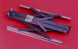
The REFLOW
RIDER has a 1.9 in (5 cm) height adjustment range to permit your profiler to be
vertically centered in the opening of your oven. Figure 1 shows the range of
height adjustments for each of the four possible orientations of the outer
rails.
Figure 1
To set the height to fit your oven:
- Measure the
distance from the top of the edge rails in your oven to the top of the highest
obstruction in the bottom of the oven which must clear the REFLOW RIDER.
- Subtract 1/4"
for clearance to get your height setting.
- Select the
configuration in Figure 1 that covers this height setting. If necessary, remove
and reattach the outer rails as shown in the configuration.
- Use the
slanted slots to obtain the exact height setting, and tighten the four screws to
lock it in.
Fit REFLOW RIDER to Your Profiler
- Referring to
Figure 2, pivot the two profiler support arms (A) out, perpendicular to the
support deck.
- Center your
thermal profiler on the arms, with its back end resting against stop (B) at the
end of the support deck.
Figure 2
- If the
profiler is less than 10 in long, pivot the arms toward stop (B)
until they touch the sides of the profiler.
- If the
profiler is more than 10 in long, the arms should be pivoted away from
stop (B) for greatest stability.
- Remove the
profiler and tighten the support arm pivot screws to lock the arms in position.
Match REFLOW
RIDER Width to the Space Between the Pin Rails
REFLOW RIDER width, measured
across the vertical side rails, should be slightly less than the space between
the pin rails.
To Set the Width Between 3 1/4 in and 14 1/4 in (8.2 cm to 36
cm)
- Leave screw
(C) snug, but not tight, at the outer end of its slot, as shown in Figure
2
- Loosen screw
(D) a turn and pull the rails (E) apart until the width, measured across the
vertical side rails, is slightly less than the space between the pin rails. The
rails should move easily when screw (D) is loosened. The other six screws in the
scissor arms are locked. Do not attempt to tighten them.
- Retighten
screw (D) to lock the rails at that width.
To Set the Width Between 14 1/4 in and 20 in (36 cm to 51
cm)
- Leave screw
(D) snug, but not tight, at the inner end of its slot.
- Loosen screw
(C) at turn. Separate the rails (E) until the width, measured across the
vertical side rails, is slightly less than the space between the pin rails.
- Retighten
screw (C) to lock the rails into position.
Note: The two
posts on the end of the support deck may be used to hold excess thermocouple
wire. The wire can be wrapped around the posts in a figure eight. The posts may
be removed if not needed.
REFLOW RIDER
is built of high quality materials, for reliable operation and long life. The
side rails, arms and support deck are hard anodized aluminum. The side rails are
clear anodized aluminum. All fasteners are stainless steel.
E-Z Rider ™
Profiling...Easier than Ever
With Your Profiler Carried
Securely
 E-Z Rider is designed to
carry your profiler safely through wave solder machines. E-Z Rider's titanium
side rails are gripped by the finger conveyors, and support the profiler well
above the solder wave.
E-Z Rider is designed to
carry your profiler safely through wave solder machines. E-Z Rider's titanium
side rails are gripped by the finger conveyors, and support the profiler well
above the solder wave.
Adjusts to
the exact width of your circuit board in seconds. Just separate the side rails
to match the width of your board, and lock them in place with the turn of a
screw. Place your profiler on the carrier, where it is securely held by tow arms
and a backstop, and slide it onto your edge rail or finger
conveyor.
SPECIFICATIONS
| Model |
E-Z
Rider |
| Width
adjustment range: |
3.25 to 20
in. ( 8 to 51 cm) |
| Profiler size range: |
Up to 6.75 in
(17 cm wide) |
| Up to 13 in (33 cm) long |
| Weight: |
0.85 lb
(390gm) |
| Side rail
material: |
Titanium |
| Arm and body
material: |
Clear hard
anodized aluminum |
| Fasteners: |
Stainless
steel |
Note: An
optional bracket is available for the E-Z Rider which allows your profiler to be
set on edge, in cases where the profiler is wider than the board it
follows.
Side RIDER ™
Profiling...Easier than Ever
With Your Profiler Carried Securely in Small
Tunnel, Belt-less Reflow Ovens
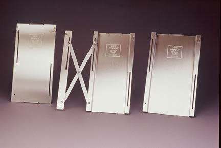
Side
Rider™, an expandable safety platform designed to carry a M.O.L.E.® or another
manufacturers Profiler securely through beltless reflow ovens that have very
tight tunnel tolerances.
Available
in two basic pan widths, 5.5" and 6.5" for different profiler models, the Side
Rider has a slightly lowered "nest" that holds the profiler assembly (profiler
in its protective thermal barrier) securely just below the level of the oven
chain, creating additional above rail top clearance of .374" (9.5 mm). This
eliminates two large problems for rail only ovens with tight tunnel space; the
profiler will not get stuck in the tunnel and it is impossible for the profiler
to fall from the Side Rider and be damaged or destroyed in the oven as often
happens using other types of carrier methods. A third 5'.5" flat pan is also
included for center rail support avoidance.
The Side
Rider platform can be used alone for narrow rail widths or with an "Outrigger";
an expandable rugged, metal frame with scissors action extension. This extender
may be used on only one side of the Side Rider, or with one on each side of the
Side Rider platform.
The Side
Rider is easy to set up: adjust the rail width to the size of the board that
will be used to set up the oven profile, instrument the board with the desired
number of thermocouples attached to the profiler. Then place the M.O.L.E. into
its thermal barrier and the whole assembly fits securely into the recessed nest
in the Side Rider platform. The profiler rides the rails securely behind the
wired board. Safely profile and characterize the oven in only
minutes.
The Side
Rider is ruggedly designed and made of stainless steel for long life. With the
Outrigger extension, it expands up to 8" (205 mm). The Side Rider is readily
available and ships from stock. It is compatible for use with all profiling
products.
SPECIFICATIONS
| Model |
E42-7433-00 |
| Width
adjustment range: |
|
| Profiler size range: |
|
| |
| Weight: |
|
| Side rail
material: |
Stainless
Steel |
| Arm and body
material: |
|
| Fasteners: |
Stainless
steel |
Board Carriers
Profiling...Easier than Ever
With A Versatile Board Carrier™
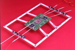 Our high quality Board Carriers
will securely hold small to medium sized circuit boards of almost any shape. And
they will support up to six TEMPROBEs for profiling.
Our high quality Board Carriers
will securely hold small to medium sized circuit boards of almost any shape. And
they will support up to six TEMPROBEs for profiling.
Quick and
Easy to Use
All Board Carriers Feature four adjustable arms. Two of the
arms can be pivoted and locked to position the board in the middle of the frame.
The two opposing arms are spring loaded to grip the board firmly and to permit
quick board replacement.
The Large
Board Carriers have two additional long arms to support the leading and trailing
board edges.
All Carrier
arms can be repositioned along the side rails to adapt to the length of the
circuit board. Standard and Large size carriers are available for Reflow and
Wave Solder Applications.
Board
Carriers for Reflow Ovens
-
The Reflow Board Carriers ride on either mesh belt or edge rail conveyors
and are compatible with edge rail conveyor grippers.
- To reflow
two-sided boards in a conveyor belt oven, simply invert the Board Carrier arms,
so the hourglass-shaped PCB grippers face us. This give 1/2 inch (1.3 cm) of
clearance between the board the and conveyor belt for bottom components.
and
for Wave Solder Machines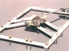
- The Wave
Board Carriers ride securely on the finger conveyors of a wave solder
machine.
- The Wave
Board Carriers are identical to the Reflow Board Carriers, except they are
manufactured of clear, hard anodized aluminum for resistance to flux.
SPECIFICATIONS
| Standard Board
Carrier |
|
| PCB size range: |
1.8 to 10.0 in (4.6 to 25.4 cm) long
0.5 to 5.3 in (1.3 to 13.5 cm)
wide
Up to 0.2 in (Up to 0.5 cm) thick |
| Outside dimensions: |
8.25 x 11.5 in
(21 x 29.2 cm) long |
| Support Arms
: |
4 |
| Sensor
Capacity: |
Up to 6
TEMPROBEs (Sold Separately) |
| Arm and body
material: |
Anodized
aluminum* |
| Fasteners: |
Stainless
steel #6-32 |
| Weight: |
0.53 lb (240
gm) |
| Large Board Carrier |
|
| PCB size range: |
2.5 to 14.0 in (6.4 to 35.6 cm) long
4.0 to 9.5 in (10.2 to 24.1 cm)
wide
Up to 0.2 in (Up to 0.5 cm) thick |
| Outside
Dimensions: |
12.0 x 15.5
in (30.5 x 39.4 cm) long |
| Support
Arms: |
6 |
| Sensor
Capacity: |
Up to 6
TEMPROBEs (Sold Separately) |
| Arm and body
material: |
Anodized
aluminum* |
| Fasteners: |
Stainless
steel #6-32 |
| Weight: |
0.65 LB (290
gm) |
Saunders
Innovations to make Profiling Easier
Introducing...
FlexiProbe™
FlexiProbe™ is designed to be used in place of a fine gauge wire
thermocouple to easily and accurately sense the temperature of solder joints
near the perimeter of a BGA during the reflow or rework process. The business
end of FlexiProbe™ is the 0.010" (0.25mm) diameter thermocouple tip. Inside this
thin stainless-steel sheath are the two tiny, insulated thermocouple wires,
which form the thermocouple junction at the sealed end of the probe. This
thermocouple tip extends out of the end of a larger diameter flexible
stainless-steel tube, which provides a convenient way of handling and
positioning the thermocouple tip. The electrical connector can be plugged into
any Type K thermocouple readout or thermal profiler.
USING YOUR FLEXIPROBE™ IS AS EASY AS 1, 2, 3,
4!
STEP 1.
Use your fingers to bend the larger diameter positioning tube to a shape that
makes it easy to slide the thermocouple tip under the BGA and have the
positioning tube lying flat on the board so it can be taped. Important: Avoid
kinking the positioning tube or bending the thermocouple tip.
STEP 2.
The thermocouple tip, though delicate, is much stiffer than a 36 gauge
thermocouple, so you can gently probe beneath a BGA until you feel it make
contact with a ball. Hold it in this position and secure the positioning tube
with a piece of Kapton® tape.
STEP 3.
Tape the positioning tube again, near its back end, to serve as a strain relief.
STEP 4.
Plug FlexiProbe into your thermocouple readout and run your profile.
®Kapton is a
registered trademark of L.E. DuPont de Nemours & Co.
 |
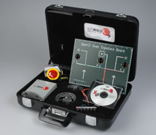
Xpert3 Painless Profiling for Perfect Oven
Recipes! |
If you already have a "Xpert Ready" M.O.L.E.®, you can download the Xpert 3 software and plan target
profiles.
- Create an OVEN signature file for your oven! No matter what model or
age!
- Designs robust profiles and develops oven settings for over
280 different pastes without leaving your office
- Transposes profiles from machine to machine, even if the ovens are
made by different oven manufacturers
- Automatically verifies that your robust target profile is actually
achieved
- Substantially reduces line set-up/changeover time while improving PCB
yield rates
- Insures identical replication of target robust profile…. machine to
machine and location to location…consistent PCB quality worldwide
- Extremely simple software interface…. makes you an instant reflow
“Xpert
|
Features / Benefits
- Out-of-the-Box Recipe Generation
- Develop the process at your desk rather than out at the oven
- Expedites Process Replication from Oven to Oven
- Reduces oven Setup Time by 60% (Real world results)
- Lead-Free Paste? No Problem!
|
AutoM.O.L.E.®Xpert-3 Systems provide the Engineer with the tools to
automatically Plan Robust Target Profiles for reflow ovens right at their desk.
The Planning and Setup stages are expedited by a feature-rich display giving
Engineers the tools to consider the oven characteristics per convection rate,
solder paste specifications, hot and cold components and laminate thickness
effects upon the assembly. Remote Recipe Development can be transferred to
manufacturing, or Auto-Predict Verification can be accomplished automatically
with the addition of the Oven Installation Kit. This kit is sold as an upgrade
[no M.O.L.E.® included] with a software unlock license for one brand [family] of
ovens. The software is covered under U.S. Patent No. 6,799,712.
Please click here if you would like to receive
more information including a working demo of the software.  |
Profile Planning and Automatic Setup |
1. Target Profile
Parameters: This Status box contains information about
the designed Robust Profile.
2. Zone Max. Deltas: Largest zone temp.
setpoint difference the oven allows
3. Typical Setpoints: These are a
range of Setpoints based on a .062" (1.6mm) board.
4. Paste Spec.
Ramp: The straight-line slope in degrees per second measured from the
intersection of the Process Origin and the Start Temp to where the profile
reaches the Soak Begin Temp.
5. Paste Spec. Soak: The number of
profile temperature values that fall between Soak Begin Temp and Soak End Temp
Times the log interval.
6. Paste Spec. Spike: The straight line slope
in degrees per second measured from where the profile reaches the Soak End Temp
to where the profile reaches a Peak temp value. |
7. Paste Spec. Liquidous: The
amount of time the profile spends above the solder liquidous
temperature
8. Zone Max. Setpoint: The highest zone setpoint that the
oven allows.
9. Paste Spec. Summary: The summary of the selected
Target Profile paste.
10. Speed Adjust: Manually adjusts the oven
conveyor speed for the Target Profile.
11. Robust
Profile Actual: Profile Parameters extracted from the Robust
Profile.
12. Target File Management: Where the
user Loads and Saves Target Profiles.
13. Transpose
Profile: Transforms an existing profile (MDM file) to a new
oven.
14. New Wizard: A wizard to guide a user to
create a new Target Profile. |
|
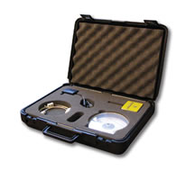
The Xpert-3 system includes:
- Software / License for one Oven Family
- Signature Board
- Desktop Download / Charging Station
- Manual
- Carrying Case
- Additional Oven Family (manufacturer) licenses may be purchased
- Kit requires a Xpert Ready MOLE which is not included
|
|
Specification
- Software Media: CD ROM - 12 Megabytes
- Operation of Xpert-3 requires access to a SuperM.O.L.E. Gold Xpert
- PC System:
- Hard Drive Free Space: 100 Megabytes
- RAM: 32 Megabytes minimum
- Processor Speed: 166 MHz minimum
- Display: 600 x 800 minimum (768 x 1024 preferred)
- COM Port: 1- RS232 (EIA Standard)
- Power (Wall transformer):
- Output: 9VDC 1.8 Watts
- Input: 120 VAC North American Plug or 230 VAC European Plug or 240 VAC UK
Plug
- Download Station: 102mm width x 127mm height x 26 mm depth ( 4 Inch x 5 inch
x 1 inch)
|
TEL :
02-868-0661
pcb21@korea.com